5 Phase Stepper Motor Driver Projects
- 10 Comments!

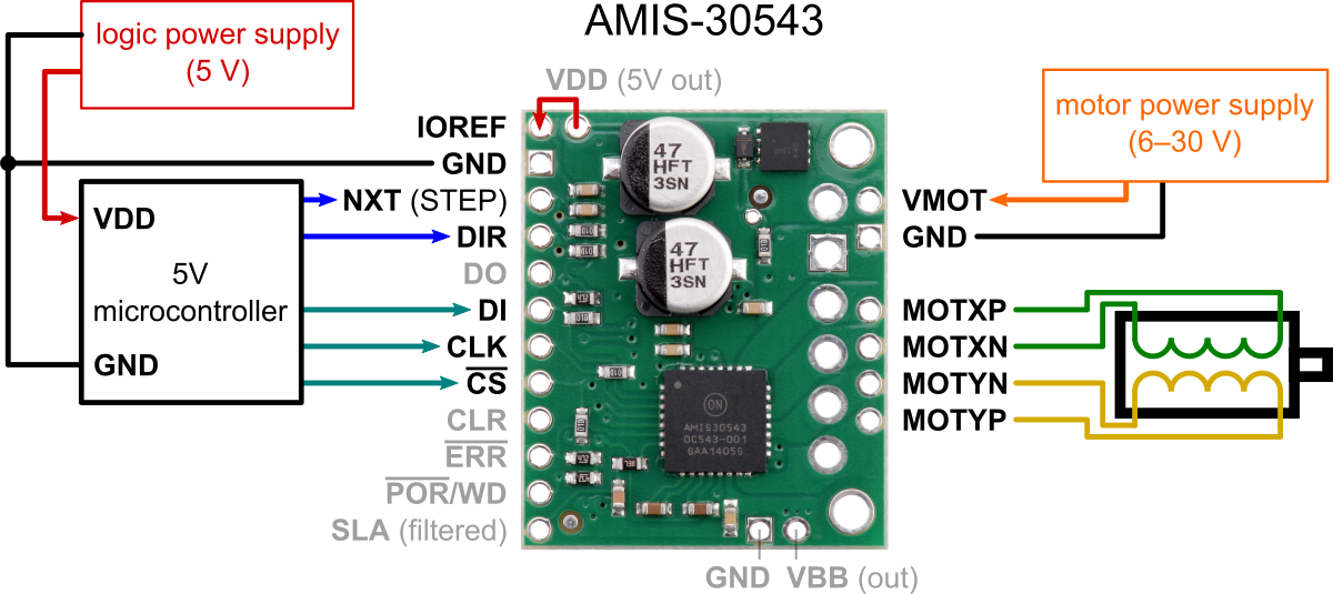
Basically there are two types of stepper motors: bipolar and unipolar. The bipolar stepper motor is a two-phase brushless motor which has two coils (windings), this motor has 4 wires (2 wires for each coil).
The other type is the unipolar stepper motor, it is 4-phase brushless motor which has 5 or 6 wires. The popular controlling modes of of the stepper motor are: full step and half step. The full step can be divided into 2 types: one-phase and two-phase. In full step one-phase mode the driver energizes one coil at a time. This type of controlling requires the least amount of power but provides the least torque. In full step two-phase mode the driver energizes the two coils at the same time. This mode provides the highest torque but it requires twice as much power as one-phase mode.
They are rated for: 1.4A at 3.22V 0.72°/step NEMA23 Now, I thought I'd design my own 5 phase bipolar stepper driver using 5 H-bridges and an AVR. I already looked at the L298 and the DRV8844. I already looked at the L298 and the DRV8844. The L9935 is a two-phase stepper motor driver circuit suited to drive. List of figures. Doc ID 5198 Rev 10. List of figures. Block diagram.
Half step mode is a combination of the two full step modes (one-phase and two-phase). This mode increases accuracy by dividing each step by 2. It requires power in-between one-phase and two-phase modes, torque also is in-between. There is another controlling type called microstepping, this type is more accurate than the half step mode, it requires two sinusoidal current sources with 90° shift. In this example I’m going to use the full step two-phase mode for controlling the bipolar stepper motor. The following image shows a simple schematic of the bipolar stepper motor: To be able to control the bipolar stepper motor, two H-bridge circuits are required.
In this example I’m going to use quadruple half-H driver which can work as dual H-bridge driver. This chip is small, low cost and easy to use, these make it a good choice for students and hobbyists, in this blog, I used it in some DC motor control projects.
In the full step control mode always both windings are energized at the same time according to the following two tables where first table shows the driving sequence for one rotation direction and second table for the other direction: Related Projects: Hardware Required: • Arduino UNO board • Bipolar stepper motor • L293D motor driver chip —-> • 10k ohm potentiometer • Pushbutton • Power source with voltage equal to motor nominal voltage • Bread board • Jumper wires Arduino bipolar stepper motor control circuit: Example circuit diagram is shown below. All grounded terminals are connected together.

The L293D chip has 16 pins with 4 inputs (IN1, IN2, IN3 and IN4) and 4 outputs (OUT1, OUT2, OUT3 and OUT4). The 4 outputs are connected to the bipolar stepper motor as shown in the circuit diagram. The 4 inputs are connected as follows: IN1 to Arduino pin 8 IN2 to Arduino pin 9 IN3 to Arduino pin 10 IN4 to Arduino pin 11 The L293D has 2 VCC pins: VCC1 (pin #16) and VCC2 (pin #8).
Two good reasons to use the handy RAPTOR software for reliability block diagram modeling using Monte Carlo techniques: 1) It’s free, and 2) A novice can use the software after 10 minutes of play-time which makes the software very productive. Raptor 7.0 is now released! 25th February 2014 Software Programs By reliass Raptor 7.0 is the culmination of two years of effort on the part of the Reliability team to enhance this already powerful tool. RAPTOR is an innovative software designed for accurate protein structure prediction. It combines advanced analysis tools in one integrated software solution and provides three different threading. 